STAR ARMY

Sci-fi roleplaying and worldbuilding community

User Tools

Site Tools


stararmy:systems:integrated_cfs_array

Integrated CFS Array

The Integrated Combined Field System Array, also known as the Integrated CFS Array or the ICFS, is a design improvement to the Combined Field System that is being used by the Star Army of Yamatai. It employs an increased measure of redundancy, more ease of replacement, and has been upgraded to improve its versatility. The system uses an array of energy fields to distort spacetime for various purposes; including propulsion (subluminal and superluminal), defense against attack as barrier-type shielding, stealth, and even limited offensive measures.

About the Integrated CFS Array

In early YE 34, members of Ketsurui Fleet Yards's Experimental Field-Systems Team joined up with technicians from Kessaku Systems to explore the concepts behind an improved Combined Field System configuration.

The system would feature a series of hull integrated grids that form sectioned arrays, eliminating the need for bulky coil systems. It also would feature a modular construction, following the current shipbuilding trends by providing a functional design that is cross-compatible between most Star Army of Yamatai starship classes. Testing of the prototype began in YE 35. In YE 39, Kage Yaichiro used the more advanced control and redundancy of the system to integrate new modes of operation, increasing the versatility of the system.

General Statistics

Propulsion Performance

In terms of propulsion functions, the Integrated CFS Array follows the Star Army of Yamatai Starship Speeds applicable for the specific class of vessel or craft.

Shield Rating

The Integrated CFS Array follows the Damage Rating (Version 3) standards for shield ratings, though some pre-YE 39 implementations might still use older standards.

Basic Characteristics

Like most CFS-based technology, the Integrated CFS Array uses various electrogravitic and electrostatic fields to create a “pocket universe” around the vessel. This pocket universe is isolated from the outside universe to a significant degree, to the point where gravity and time do not impact it in the same way once the fields are in place. Even energy and mass, often in the forms of enemy weapon discharge, are curved around the distorted space around the edge of the field provided enough energy exists in the system to do so.

Because of its ability to isolate the ship from normal reality and the ability to operate outside of regular spacetime; the Integrated CFS Array is used for subluminal propulsion, superluminal propulsion, protection, stealth, and in some cases offense. It is almost always on to some degree because of its versatility; though it is necessary to make holes in the CFS temporarily to allow for unobstructed weapon discharge, exhaust from supplemental subluminal propulsion systems, or the deployment of equipment and vehicles.

The Integrated CFS Array can also be used to generate waves and pulses, which can be used to detect hidden ships and objects when used in combination with the sensors.

Integrated CFS Array Monitoring and Energy Control

Using standard internal and external sensors, the ship's quantum computer can monitor the Integrated CFS Array both at the field and at the generators inside the ship. Due to this, a computer can extrapolate the precise energy flow around the ship and predict where the energy will be redirected to along the CFS, be it radiation or weapons fire. It can also be used to monitor the status of the ship’s barriers precisely, diagnose problems early on, and be used in conjunction with other programs that require the state of the Integrated CFS Array. It should be noted that since this requires internal measurements from the ship's generators, it can only be used upon one’s own CFS or Integrated CFS Array and not those of others.

Since the ship's PANTHEON Integrated Electronics System can determine the state of the CFS at any given time and even extrapolate where energy will be redirected to along it, it is possible to use that data to compensate for the CFS' effects when firing energy weapons and even redirect the shot along the surface of the CFS to the desired location. This allows multi- or omni-directional energy weapons, as well as the energy weapons of Power Armor, to accurately target and hit enemy targets while inside of and using the CFS.

Limitations

The Integrated CFS Array has some of the same limitations as the original CFS. It is not possible to change the direction the vessel is facing with the Integrated CFS Array alone, leaving turning and rotation to conventional thrusters. This becomes a matter of consideration when bringing weapons to bear. It should also be noted that strong enough gravity can influence the field to where the isolation from time is partially counteracted and superluminal transit is not possible. This chiefly occurs when in the vicinity of a star system, but can also be caused by artificial sources of gravity such as Graviton Beam Projectors.

It is also possible to overwhelm the field with weapons to the point where the barrier's energy is depleted faster than it can be replenished by the vessel, exposing the vessel to potential harm. This is potentially compounded by the fact that the Integrated CFS Array must share its energy between propulsion and protective barriers. A ship using 80% of its Integrated CFS Array's energy for its barrier only has 20% of its top superluminal speed, and using the CFS to project energy beams for offensive purposes depletes this energy pool further. It common to have a secondary subluminal propulsion system for combat purposes, to divert 100% of the Integrated CFS Array's resources to protection.

A unique limitation to the Integrated CFS Array is that in some particularly small craft such as Power Armor, the Integrated CFS Array is less able to grant high superluminal speeds because of a lack of room under the armor for the system or a limited number of panels in relation to armor geometry. This can result in some units with little or no FTL capability or even a lack of Integrated CFS Array compatibility outright, depending on circumstances. Some smaller systems also lack the self-repair function or sheer redundancy of normal Integrated CFS Arrays, due to lack of HSCS-3 systems to connect to and the reduced number of panels respectively.

Hull Integration

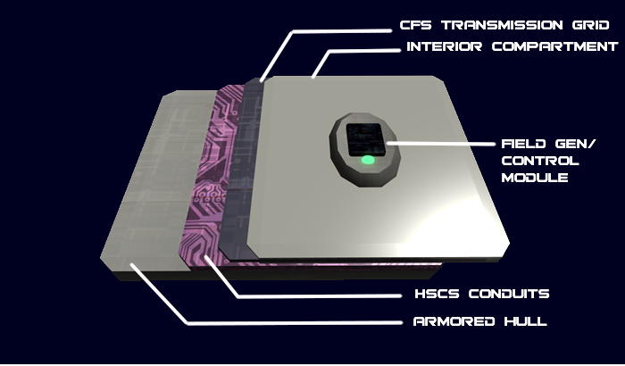
Arrays form an additional hull layer, beneath the armor plating of the vessel. This layer does not provide any additional strength to the hull. The arrays are also interconnected with the Hemosynthetic Conduit System's HSCS-3 for automated repair. Repair time is dependent on the size of the array section. The field and control modules can be swapped in and out by authorized Star Army Engineers.

In YE 43. the Hemosynthetic Conduit System was replaced by the Nodal Liquid Conduit System which would have taken over this same function.

Integrated CFS Array Components

Various components are needed to make the Integrates CFS Array function, though they are heavily integrated together and easy to replace if needed.

Field Generation and Control Modules

The field generation and control modules are positioned in each array section. The number of these modules is dependent on the size of the ship and are connected to the ship's power systems and the respective PANTHEON IES system installed on the vessel. The modules convert the ship's power into electrogravitic and electrostatic fields and can form continuum distortion fields which are transmitted through the CFS transmission grids. Modulation and augmentation is controlled by the IES and from the appropriate station on the bridge, such as Systems and Safety Monitoring.

Improved Control

The placement of Field Generation and Control Modules assists the IES in being able to divert power to increase CFS to the areas of the ship that require improved defense. Power can also be diverted through the arrays to compensate for damaged sections of the system. Adjacent undamaged areas can also act as containment force fields to seal hull breaches.

Maintenance and Repair

Modules are accessible from Standard Star Army Maintenance Conduits and require regular diagnostic and replacement by Star Army Technicians and Engineers. Modules should be checked once a week and replaced at six month intervals.

During combat operations, damaged modules can be swapped in and out with replacement units. Spare units are found at Damage Control Stations.

CFS Transmission Grid Layers

The CFS Transmission Grids that are connected to the Field Generation and Control Modules are composed of a synthetic crystalline structure which form wave-guides that assist in controlling the field's projection around the hull of the ship. Each grid is composed of major and minor latticework which ensures strong, redundant and continuous connections. This also makes each grid compartmentalized which assists with maintaining CFS function when the ship is taking damage. These grids are arranged in layers providing redundancy.

More on Grid Repair

The CFS only truly becomes vulnerable when the armored hull layers above it are destroyed. The synthetic crystalline structure of the grid is a material that is able to be repaired through the deployment of the Hemosynthetic Conduit System's HSCS-3 through networked channels that run through the grids. Grids can also be swapped in and out by Star Army Technicians and Engineers.

It should be noted that some smaller vessels lack the Hemosynthetic Conduit System, which removes this self-repair capability from some applications.

Deflector Clusters

The Deflector Cluster is a structure of clustered CFS Transmission Grid Layers and Field Generation and Control Modules. The cluster allows for the easy augmentation of the field, which protects the ship from debris and it eliminates the need for an independent Continuum Distortion Drive unlike some other implementations of CFS. Through precise modulation and augmentation of the distortion fields the Deflector Cluster can be utilized to form generating small wormholes, navigating the quantum slipstream, and acting as STL and FTL propulsion. Craft with only one cluster have it situated in the front of the ship as a Forward Deflector Cluster, typically somewhere along her center line.

Multiple Clusters

Rather than having simply one forward-facing Deflector Cluster, some vessels and structures have multiple clusters. These usually provide redundancy to allow a warship to function even if a cluster is hit, and are common on vessels with nacelles that once stored a conventional CDD or CFS. It is not uncommon for a vessel to have two Nacelle Deflector Clusters and one Forward Deflector Cluster for redundancy, but this is not commonly interpreted as a multi-faced barrier unless there is sufficient power for this purpose.

Vessels that have six such clusters for six-faced barrier configurations tend to have one each port and starboard (often on the nacelles of the vessel if applicable), one each fore and aft, one on the ventral surface, and one on the dorsal surface. There may also be a seventh for main weapon control. This, however, requires sufficient power reserves. On Star Army of Yamatai Star Fortresses and bases that chiefly use six-barriers, these clusters are situated at key points on the hull depending upon the structural design to achieve these six directions.

Integrated CFS Array Resource Allocation

Control of the CFS functions is through the IES and from the appropriate station on the bridge (such as Systems and Safety Monitoring), or other authorized connection. The CFS is always operating, unless it is taken offline for major repairs and/or refit.

Field Balance

As the same systems and energy reserves are used for propulsion and barriers, the field must be balanced between these functions and can't utilize both to their maximum. For example; if the ship is operating at 20% of its maximum FTL speed, it leaves 80% of the field's resources to be utilized for other functions such as barriers and Projected Energy Beams. It is common simply to refer to the speed and barrier balance because Projected Energy Beams are not regularly nor continuously used, and other secondary functions do not deplete the field's energy in the same manner.

Field Balance is also determined by the Star Army Readiness Conditions, which dictates how much of the ship's field is to be allocated toward speed and how much is to be allocated towards the barrier.

Two-faced Barriers

A two-faced barrier allows 200% power distribution and twice as many emitters to make two facings, fore and aft. Energy for speed and for barriers can be shared between the facings freely at any proportion. It is possible to have increased shielding on one barrier at the cost of another, changing 100% / 100% into 50% / 150%, for example, or maintaining 100% to speed while having 50% shielding on both barriers. It is also possible to allocate 100% power to speed for maximum FTL capability and still have 100% to allocate to the shields, likely in a 50% / 50% mix.

These types of barriers are meant for things larger than Power Armor; like mecha, starfighters, and some shuttles.

Six-faced Barriers

Field Balance to a six-faced barrier is more complex due to a number of factors. These barriers have six distinct sides, each with 100% energy reserves. These reserves can be re-distributed between each other like in two-faced barrier configurations, but no facing can exceed 200% energy without risk of damage to the Integrated CFS Array. Each facing must contribute a sixth of its energy to achieve top FTL speed, or one facing must contribute 100% of its energy alone. A vessel can thus travel at maximum speed while maintaining up to 5/6ths of its energy reserves for each facing's barrier, which can then be re-allocated as needed within the 200% energy-per-facing limitation.

It is possible for a single facing (or a few together) and emitters to take the full burden of FTL speed; but this is not standard practice unless there is a specific circumstance necessitating it such as damage to a facing, or unless a facing's emitters would otherwise be pushed beyond 200% after considering shielding.

It should be noted that the the Integrated CFS Array integrates CDD function into itself fully and removes the coil assembly, so more than 100% speed is theoretically possible if such energy is allocated. However, it is quite unsafe and risks burning out various systems if used. It should only be used in desperation and if Propulsion Modulation is for some reason unsuitable for a task.

Two-faced Interpretation of Six-faced Barrier

Please note that six-faced barrier energy distribution is sometimes simplified into two facings for ease of control and reference in combat (fore and aft, changing 600% total to 200% total), though the weight of each percentage point allocated to shielding or barriers is three times more significant due to the integration of three barriers and sets of emitters into one control system. This makes computation difficult without translating to six-faced operation, but a rule of thumb is that a weapon of a matching Tier to the Defensive Tier of the equipped ship can down the barrier in two shots, and hit the vessel inside the CFS in a third. Otherwise, this simplification is similar in function to standard two-faced barrier offerings.

A benefit of this management system is that it is not possible to push the emitters beyond 200% – the computer system and Deflector Clusters interpreting the commands to the six-faced barrier system will automatically allocate the emitters and energy optimally.

Integrated CFS Array Functions

The Integrated CFS Array provides Star Army of Yamatai starships multiple functions from defense to propulsion. Various other advantageous functions achievable by utilizing the “pocket universe” are also included.

Propulsion

Propulsion function is provided in conformance with the Star Army of Yamatai Starship Speeds standard.

The Integrated CFS Array can be utilized to preform the function of a Continuum Distortion Drive, unlike some other CFS offerings. Continuum distortion fields are augmented through the Deflector Clusters to form asymmetrical peristaltic fields. This allows for subluminal to speeds thousands of times the speed of light.

The Integrated CFS Array is also capable of generating small wormholes, navigating the quantum slipstream, creating hyperspace fold points, and acting as sublight propulsion. Distortion-based systems allow the ship to stop or move with acceleration greater than conventional systems, as the ship has not “moved” in the technical sense. However, it is incapable of rotating or steering a ship, with the vessels retaining their facing. As a result, this task is left to more standard propulsion systems.

Propulsion functions can be affected to the point of losing FTL capability by strong gravitational influences such as those of star systems. They can also be affected by Graviton Beam Projectors, but only if the projectors manage to ensnare the Integrated CFS Array-equipped vessel before it escapes.

Propulsion Modulation

Propulsion Modulation is a randomization component added to the Integrated CFS Array for use in superluminal operation. It takes advantage of the fact that the vessel is not accelerating and would not experience ill effects at abrupt or rapid changes. It is possible to reduce the speed of the vessel with a semi-random value within a certain range, adding a range of uncertainty to the position the vessel. This is to prevent enemy interception or ramming, even if the enemy should be faster. It is not available at subluminal speeds. As visible from the chart below, this can make a ship's position vary notably even in a single millisecond. Of course, as this is a range, an evasion is not an absolute certainty.

FTL Speed Modulation
Default Range of Play Intended speed minus 0c - 1000c
Uncertainty Range per millisecond 0 km - 299,972 km
Uncertainty Range per second 0 km to 299,972,000 km (~2 AU)

It is also possible to adjust the heading of a vessel with various degrees of pitch and/or yaw. Two degrees of play is the default setting. This degree of change is only semi-random, as the overall end destination must be the same and travel time must be reasonable, but it is still sufficient to keep the vessel from traveling along a precise predictable path. Note that this does not change the ship's orientation within its CFS bubble. It merely changes the movement of the bubble itself.

Defense

Defense functions are provided in conformance with the Damage Rating (Version 3) standards for shield ratings, though some pre-YE 39 implementations might still use the older standards.

When the CFS resources are allocated to defense, the nested electrogravitic, electrostatic and distortion fields around the ship are controlled the respective PANTHEON IES, with manual adjustment available from the Systems and Safety Monitoring station on the bridge, to allow and compensate for the firing of the ship's weapons as well as determine the state of the CFS.

Primary Defense

The nested fields create a pocket universe around the ship, wherein temporal and gravitational fields do not affect objects within the distorted/curved space around the vessel in the context of defense. This provides and effective defense against both solid and energy weapons as well as meteors and ramming attempts. The ship's respective PANTHEON IES can rapidly divert energy to a predicted impact/effect zone or manipulate the field shape and frequency to provide superior defense against weapons fire and natural hazards. The field also protects the ship from impacts from natural debris or debris from destroyed ships during STL and FTL transit.

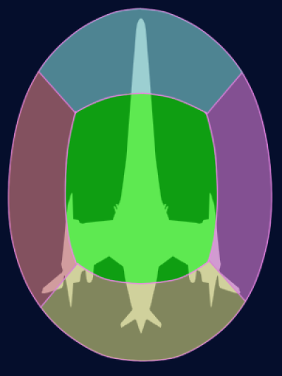
In YE 39, the shapes of these fields were made more variable with assorted modes to take advantage of the abilities of the CFS. Unfortunately, it is only possible for the ship to extend its CFS to four times the equipped vessel's longest dimension (or two times standard size in all three axes) due to energy constraints, and even then the strength of the barrier is reduced proportionally to as low as 25%.

Shield Type Description
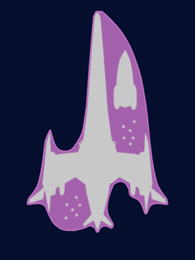
Bubble Mode This form uses a sphere or ellipsoid to cover a maximum volume given a specific surface area and risks being struck and depleted by shots that would otherwise miss the equipped vessel. While it may be inefficient when used conventionally, it can be effective if used to protect Power Armor or smaller vessels traveling with the craft, as well as if the vessel has a complex geometry that makes Conformal Mode less practical due to an increased surface area.
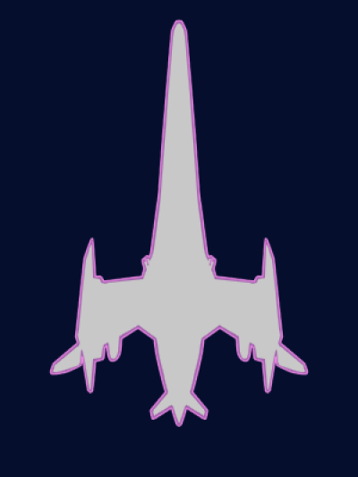
Conformal Mode In this state, the shield operates in the opposite manner and covers the minimum volume possible by conforming to the shape of the hull precisely. Thus, shots which would miss the ship almost always miss the shield. It is most suitable when the ship does not need to protect anything else, but its protective efficiency will degrade if the ship has a large number of protrusions or complex shapes that add to its surface area. An increase in surface area to the shield means a proportional increase in energy needed to maintain it. This is most evident in practice if the vessel is struck by a wide-area energy blast.
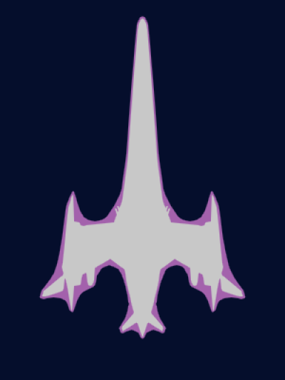
Streamlined Mode Less energy is required to maintain the same shield strength when minimizing surface area, so this form seeks a compromise between volume and surface area that largely achieves the benefits of both Bubble and Conformal Modes. The shield wraps around the ship in a manner not dissimilar to if it was vacuum-sealed in plastic. This still allows enough space in some designs to protect and transport deployed Power Armors and/or Fighters.
Variable Mode It is possible to configure the shape of the CFS as needed for various purposes. These include extending the CFS around weaker or damaged allies, helping transport such vessels or allies, or even move while docked to another ship at the cost of field strength. Due to the various sizes and formations of craft that might need protected, the Variable Mode is quite diverse in its application. The strength of the CFS is weakened, however, if the surface area exceeds certain parameters.
Six-Faced Barrier This barrier configuration for the CFS and the modes above are not mutually exclusive. Any of the above modes can be used with a six-faced barrier version. The six-faced barrier simply has independent barrier strength fueled by an independent power source for each of the six faces: Fore, Aft, Port, Starboard, Dorsal, and Ventral. Sometimes these are simplified into Fore and Aft for ease of management. Each of the faces must have at least one Deflector Cluster as well. Energy and geometry can be shared between the barriers, but it is unsafe to strengthen any face of the barrier past 200% at the risk of damaging the system. This barrier is usually only seen on state-of-the-art vessels, capital ships, and bases.

Though there are limitations on how far a barrier can be extended due to surface area, there are certain cases in which extending a barrier is practical. Often these are used in cases of emergency, or when escorting allies or damaged vessels. Please note that in vessels that have complex geometry, Power Armor Teams may be able to find locations of protection without requiring the extension of the CFS to the point of depleting barrier strength.

Percentage of Barrier Size Relative Volume Relative Surface Area Maximum Strength/Speed Common Purpose
122% (all axes) ~183% ~150% ~75% Protection and transport of Power Armor
144% (all axes) ~300% ~200% ~50% Protection and transport of smaller craft and Power Armor
200% (all axes) 800% 400% 25% Transport of smaller craft and Power Armor in maximum possible volume
150% (longest axis) 150% 150% 75% Transport of smaller craft or Power Armor
200% (longest axis) 200% 200% 50% Unsafe transport of one craft of same size
250% (longest axis) 250% 250% 40% Safe transport of one craft of same size
300% (longest axis) 300% 300% 33% Unsafe transport of two craft of same size
350% (longest axis) 350% 350% 28.5% Safe transport of up to two craft of same size
400% (longest axis) 400% 400% 25% Unsafe transport of up to three craft of same size

Aerodynamic Effects

A side effect specifically of Streamlined Mode (and in some cases Conformal Mode if hull geometry is simple enough) is that balancing the surface area and volume makes the CFS more aerodynamic in a gas or liquid. As such, the vessel may see an increase in mobility as well as structural integrity in planetary operations. The increase in mobility is not only due to the ability to increase the top speed of many craft that are not already optimally aerodynamic (typically up to Mach 5), but also the direct result of the ability to vary the geometry of the craft and use any part of the shield as a possible streamlined control surface.

If the vessel's CFS collapses due to enemy fire while bolstering the vessel's geometry to move at a pace beyond what its structure could normally support through a given medium, it may result in damage or destruction of the vessel. As such, it is recommended to use appropriate speeds while planet-side if the CFS' strength is weakened.

Outer Field Properties

The outer boundary of the field is an intense scalar field which serves to dud electronics of incoming missiles, armors and other small craft, as well as detonating explosives, ablative armor, and overloading the nervous systems of pilots. This feature is disabled during normal operations, and (usually) enabled in combat.

Stealth

The ship can also be rendered invisible to scalar radar, aetheric-energy sensors, and other forms of detection by using the shield bubble to keep the ship in its own alternate plane of existence. It can also use its scalar fields to simulate that photons and other sensory forms pass through the “empty space” and thus its presence is hidden. When the ship is fully in its bubble plane, it may only use its RDD sensor to monitor normal space; all other sensors will be useless.

Defense against Phasing

Star Army of Yamatai ships and stations have been able to counter “phasing” since YE 27. No phased object or creature may penetrate a CFS shield bubble.

Electronic Warfare

In conjunction with the Type 31 Electronic Warfare Suite, the CFS can be utilized to direct electromagnetic, electrogravitic (scalar), or distortion pulses to disrupt sensors or to throw off distortion-based sensors, and mass sensors.

Weapons

Craft equipped with the Integrated CFS Array also can use it for offensive purposes. This is either as a weapon in and of itself in the case of Projected Energy Beams or as a method of redirecting existing armaments in the case of Discharge Redirection.

Projected Energy Beams

This system is the classic ability for the CFS to redirect energy multi-directionally or omni-directionally across itself and at an enemy. It was first employed as part of the Yuumi-class Battleship program. It uses the CFS' spatial distortion properties to connect to the Aether and allow a beam of energy to lance out at an enemy at just under light speed. The source of energy can be along any point on the CFS, though this takes large amounts of available energy away from propulsion and shielding. This is especially true as more beams are employed. As such, it is best used against smaller targets or to supplement debris deflection duty for the CFS. It typically is not very useful against shields of comparable power and size or larger. It has fallen out of favor due to these limitations, but still has its uses.

  • Location: Integrated Combined Field System
  • Purpose: Variable Tier1 | Light Anti-Counterpart
  • Secondary Purpose: Debris Deflection
  • Area of Effect: Beam of 1 to 25 meters in diameter2
  • Range: Theoretically unlimited except by the beam's speed (just under 1c)
  • Rate of Fire: Up to ten five-second blasts every 15 seconds3

1 The Tier of the Projected Energy Beam is typically two under the Defense Tier of the specific unit on which the Integrated CFS Array is installed. It is thus useful against its contemporaries to a limited degree. This is under the Damage Rating (Version 3) standard.

2 The maximum diameter of the beam cannot exceed 25% of the length of the vessel.

3 The faster the recharge time, the weaker the Integrated CFS Array's propulsion and shielding capability.

Discharge Redirection

The newer second mode actually uses the Integrated CFS Array's finer control to manipulate space and gravity in front of a weapon or exhaust plume in a way similar to how the barrier deflects incoming shots, plus some gravitic field manipulation to adjust the discharge's orientation in relation to the ship. This allows the discharge path to curve rather than go straight in relation to the vessel the CFS is anchored to and permits formerly line-of-sight weapons to hit targets at different angles, as well as improved turret firing solutions and less strict turret placement. The computer systems of a vessel can also use this mode for last-moment fine course corrections after the munition has already been discharged. This function is limited to within the range of the CFS around the vessel, but even that is sufficient to significantly alter trajectory and give a greater functional firing arc to a weapon.

Unfortunately, this comes at a cost. Moving the weapon discharge typically causes depletion to the barrier appropriate to the Tier of the weapon, except in cases of encapsulated antimatter and explosive which are only the cost of redirecting the shot instead of the resultant explosive (antimatter-encapsulated rounds cause no more barrier damage than matter ones in this case). As such, this should only be used regularly with weapons below the threshold of the barrier(4 Tiers below), such as the Ke-S3-W3102 Star Army Anti-Fighter Turret, Type 31 on a Plumeria-class (2D) Medium Gunship. It is also possible for a vessel with a powerful enough Integrated CFS Array to use this function for brief but extreme emergency thrust-vectoring capabilities with its Turbo Aether Plasma Drive Drives (Tier 9 - 11), at the risk of shaking up the occupants. It should be noted that this is a more extreme and dangerous thrust vectoring capability than other in-built options.

OOC Notes


Quality:
stararmy/systems/integrated_cfs_array.txt · Last modified: 2023/12/21 01:02 by 127.0.0.1